- 01Operating configuration & geometry
- 02Solid mesh & quality
- 03Contacts & boundary conditions
- 04Acceleration & braking
- 05Global stresses & local diagnosis
- 06Displacements, reactions & conclusion
Stage 01Operating configuration & geometry
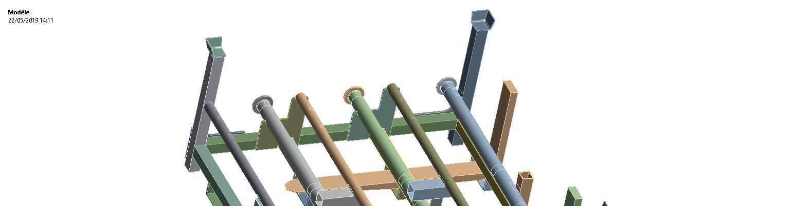
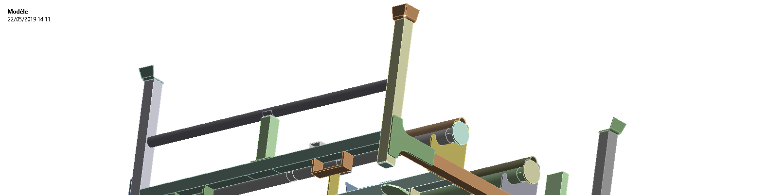
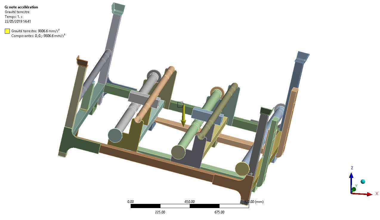
Representation of the lower platform, stacked upper platform, inclined forks and six transported loads as point masses connected to the structure.
Model data2 platformsStacked configurationLower platform calculated and upper platform represented by mass
Model data6 × 137.5 kgTransported payload825 kg total
Model data12°Maximum inclinationCritical transport configuration
Technical review points- Technical objective
- Interfaces
- Acceptance criteria
Stage 02Solid mesh & quality
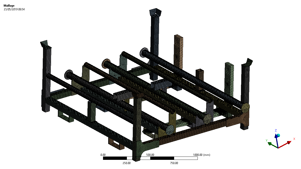
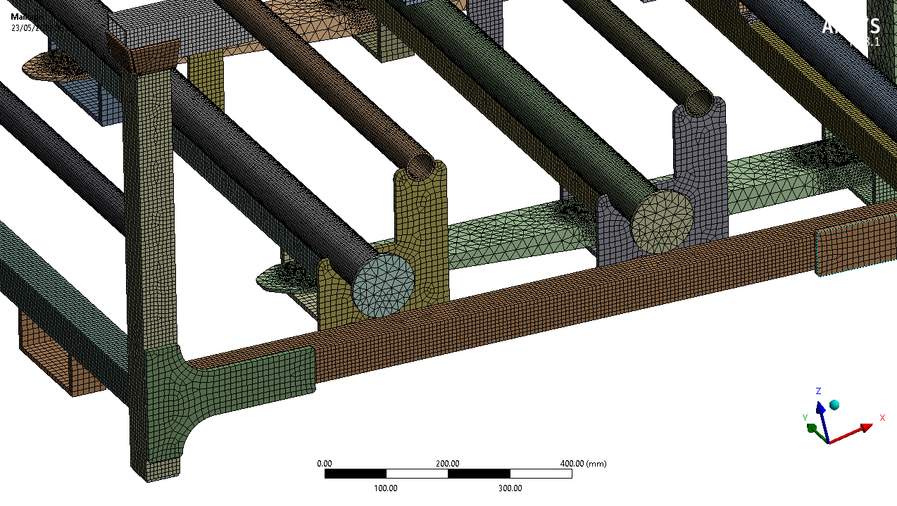
Hybrid hexahedral and tetrahedral mesh, refined on cylindrical tubes and adapted to the stiffeners, with checks on transitions and element quality.
Model data5 to 10 mmElement size5 mm on tubes · 10 mm on stiffeners
Model dataHexa + tetraSolid meshGeometry-based refinement
Model dataS235JRStructural materialRe = 235 MPa
Technical review points- Technical objective
- Interfaces
- Acceptance criteria
Stage 03Contacts & boundary conditions
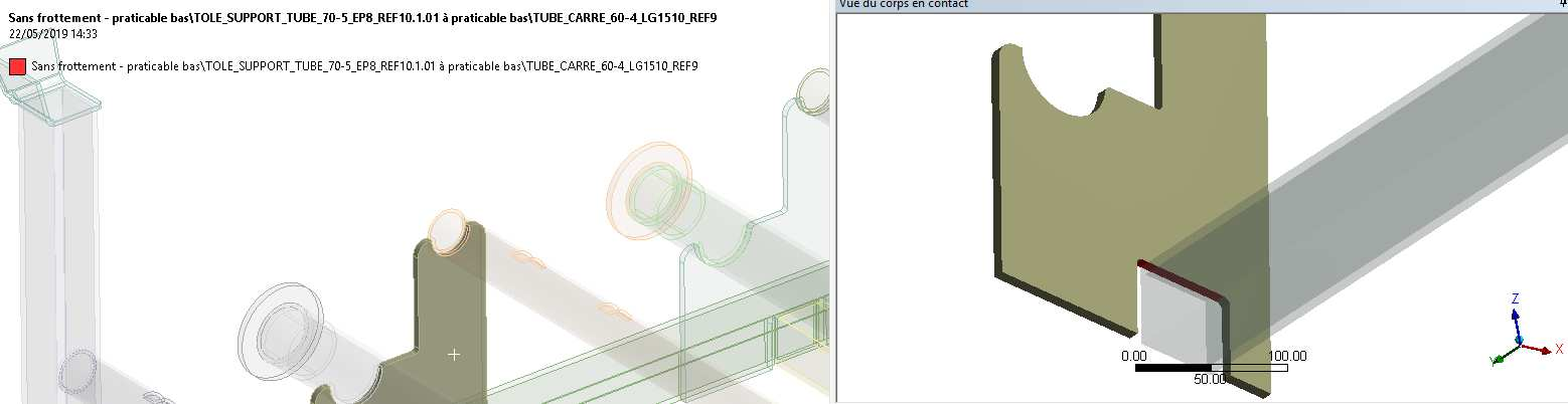
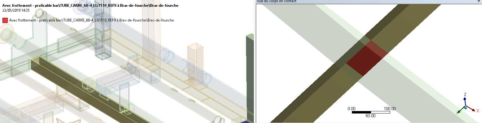
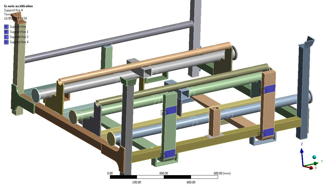
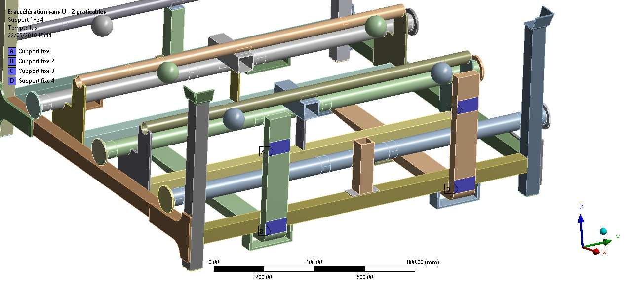
Definition of contacts between tubes, stiffeners, forks and masses, followed by restraints representative of platform retention on the truck during transport.
Model dataBonded contactsStructural assembliesContinuity between welded components
Model dataForks + stopsRetention interfacesTransport supports and restraints
Technical review points- Load cases
- Boundary conditions
- Mechanical response
- Reviewable results
Stage 04Acceleration & braking
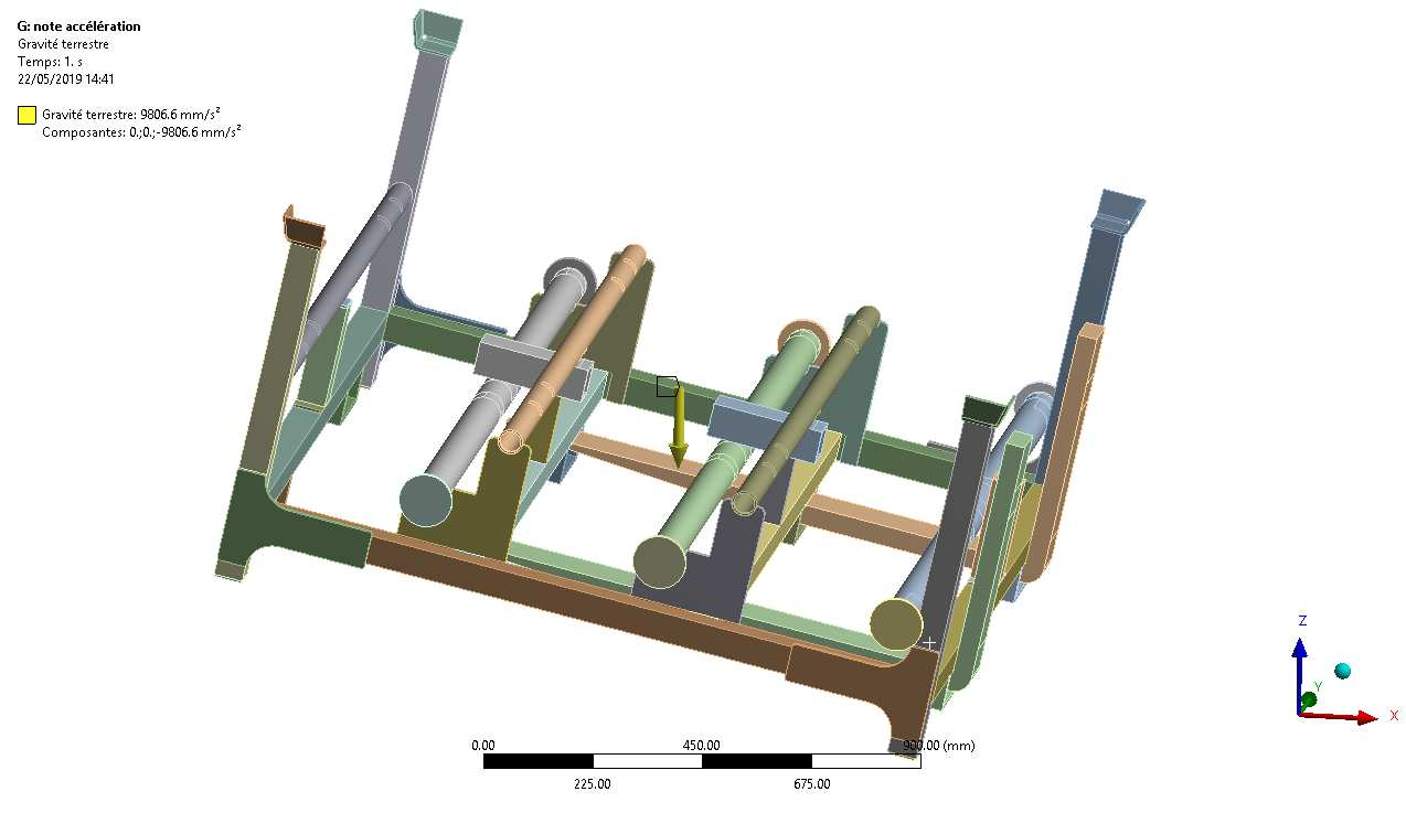
Two unweighted load cases reproduce the critical cycle phases: tipping under acceleration and retention on the forks during braking, including gravity and transported masses.
Model data5.2 m/s²Case 01 — accelerationPlatform tipping
Model data4.9 m/s²Case 02 — brakingRetention on forks
Model data1 gSelf-weightGravity applied to the structure
Technical review points- Technical objective
- Interfaces
- Acceptance criteria
Stage 05Global stresses & local diagnosis
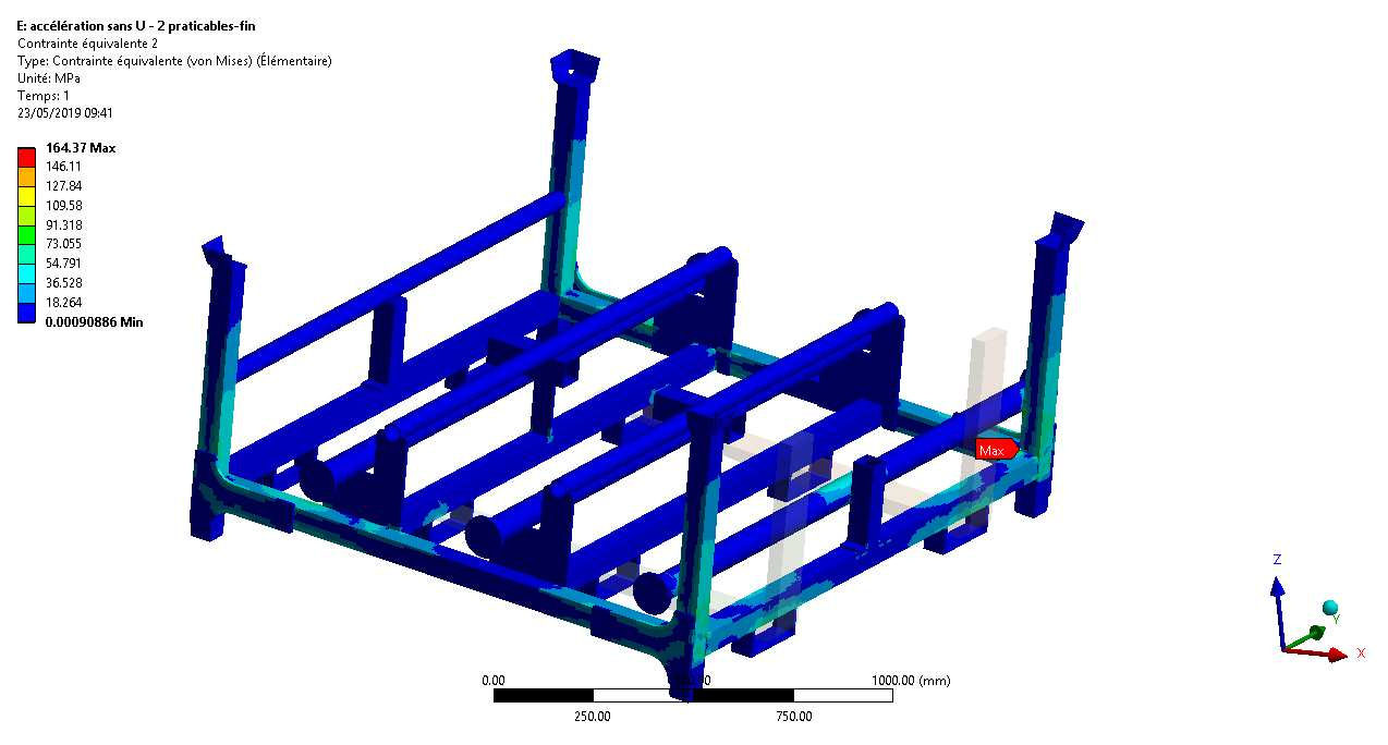
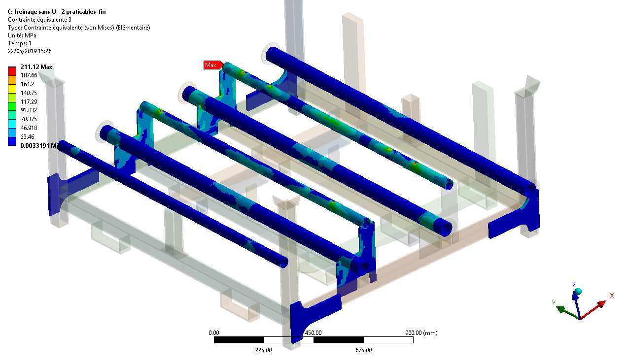
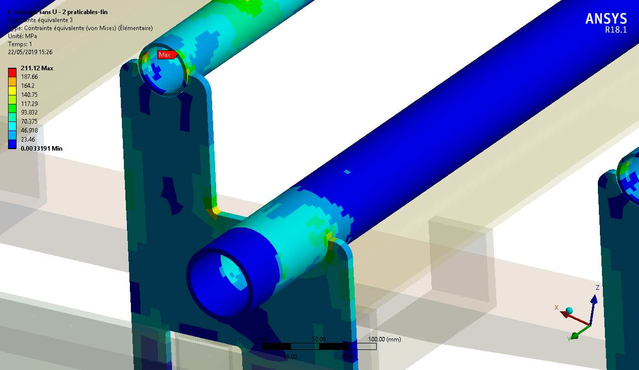
Comparison of Von Mises fields for both phases. The slight exceedance in the braking case is isolated to a very local area and analysed separately from the global structural response.
Validated164.37 / 235 MPaAcceleration case — S235JRMaximum / allowable stress
Model data235.93 MPaBraking case — local pointLocalised exceedance analysed
Model data235 MPaReference limitS235JR allowable stress
Technical review points- Technical objective
- Interfaces
- Acceptance criteria
Stage 06Displacements, reactions & conclusion
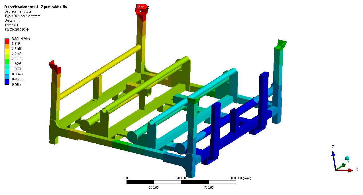
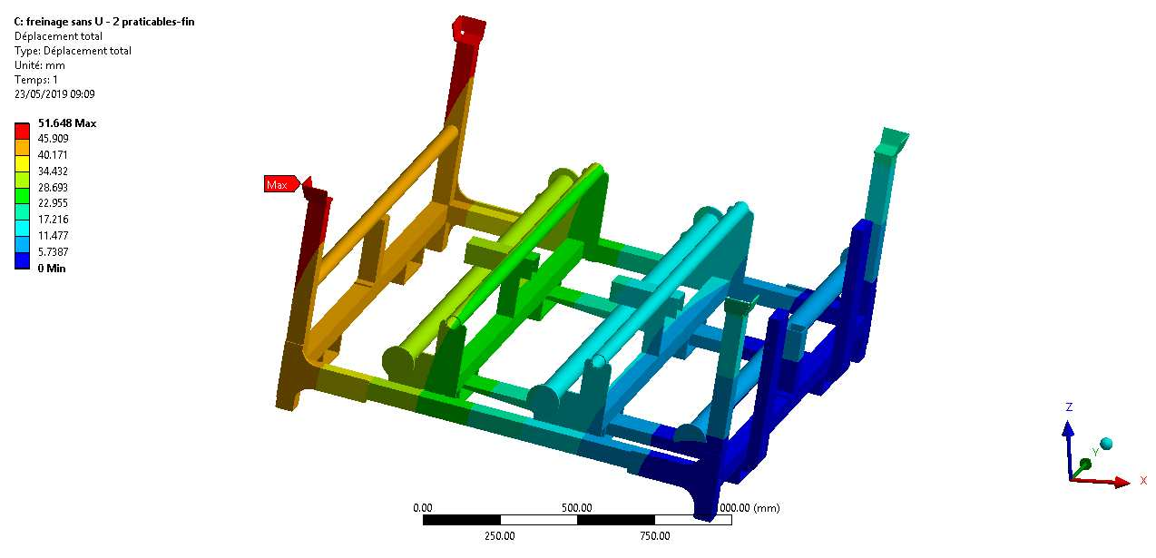
Review of maximum displacements in each phase, extraction of interface reactions and assessment of overall platform strength under the defined operating conditions.
Model data3.62 mmDisplacement — accelerationGlobal response for case 01
Model data51.65 mmDisplacement — brakingGlobal response for case 02
Model dataFx · Fy · FzExtracted reactionsForces at connections and supports
Technical review points- Technical objective
- Interfaces
- Acceptance criteria