- 01Calculation geometries & shell models
- 02Mesh & refinement areas
- 03Contacts, connections & boundary conditions
- 04Load cases & self-weight
- 05Lifting-beam stresses & displacements
- 06Lifting plates & assemblies
Stage 01Calculation geometries & shell models
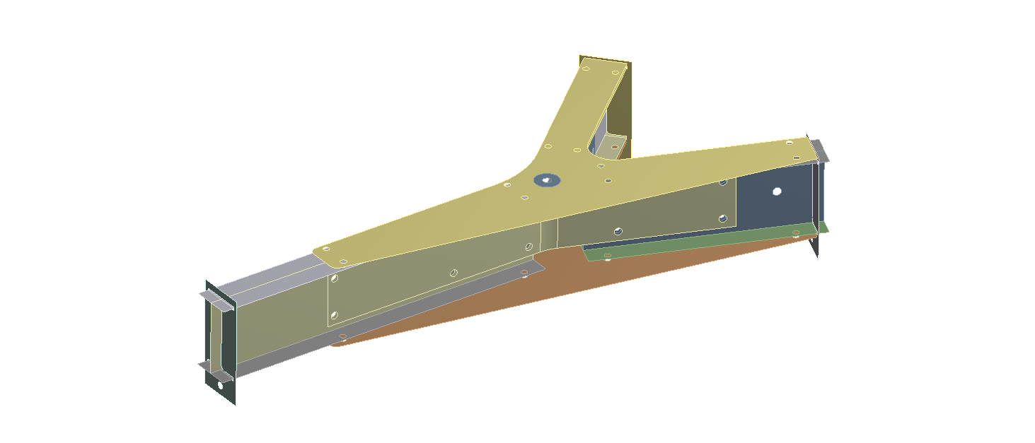
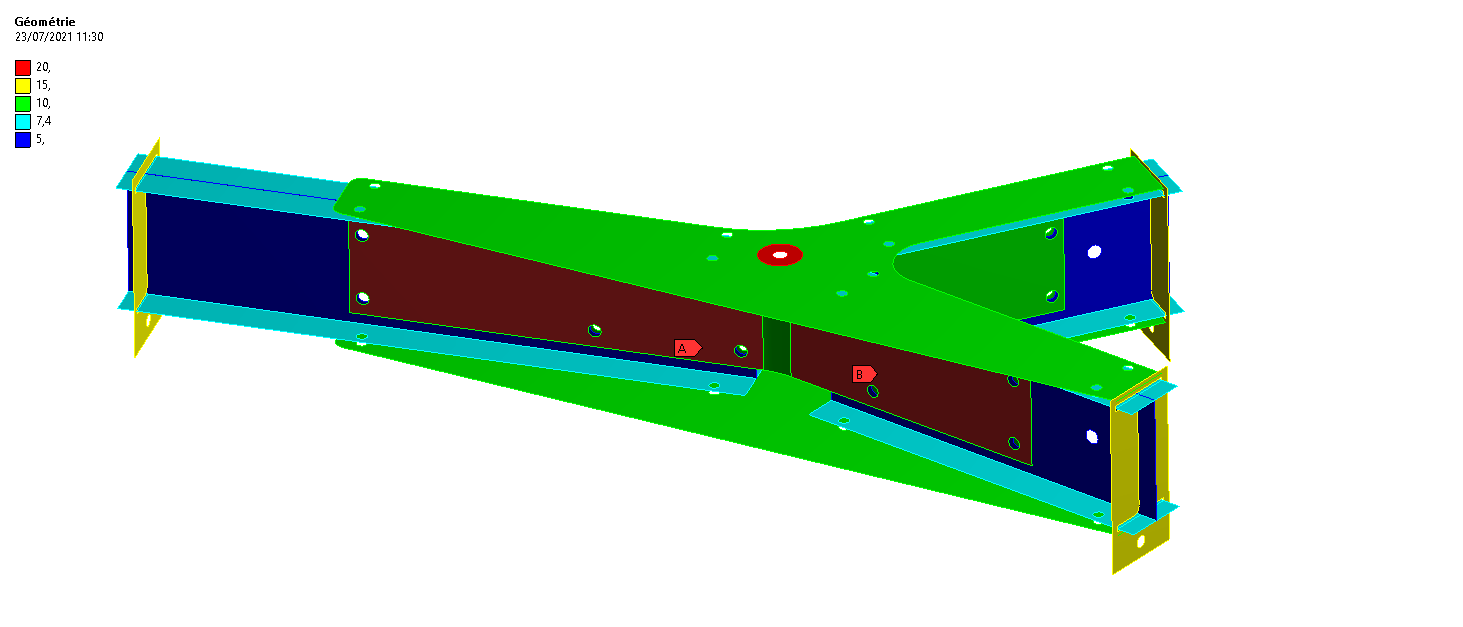
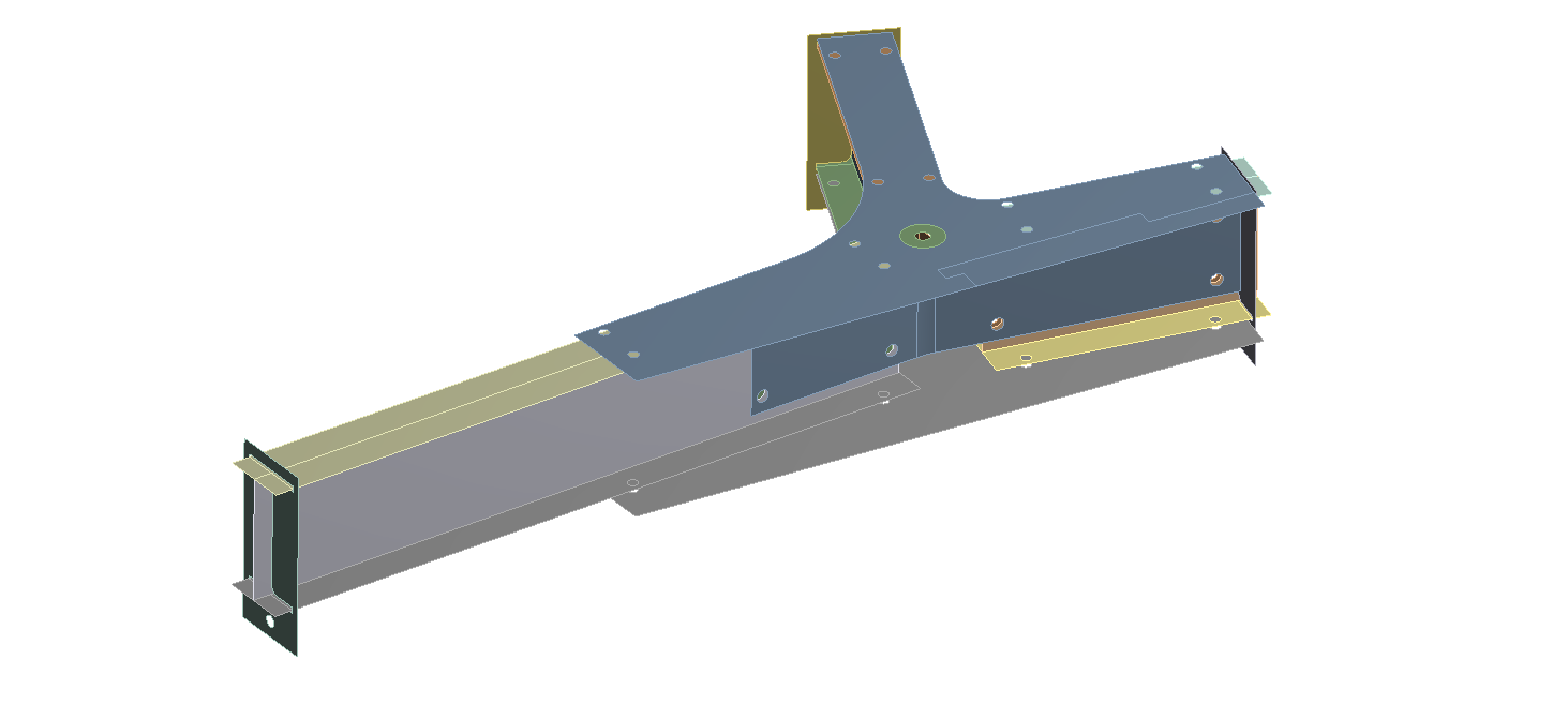
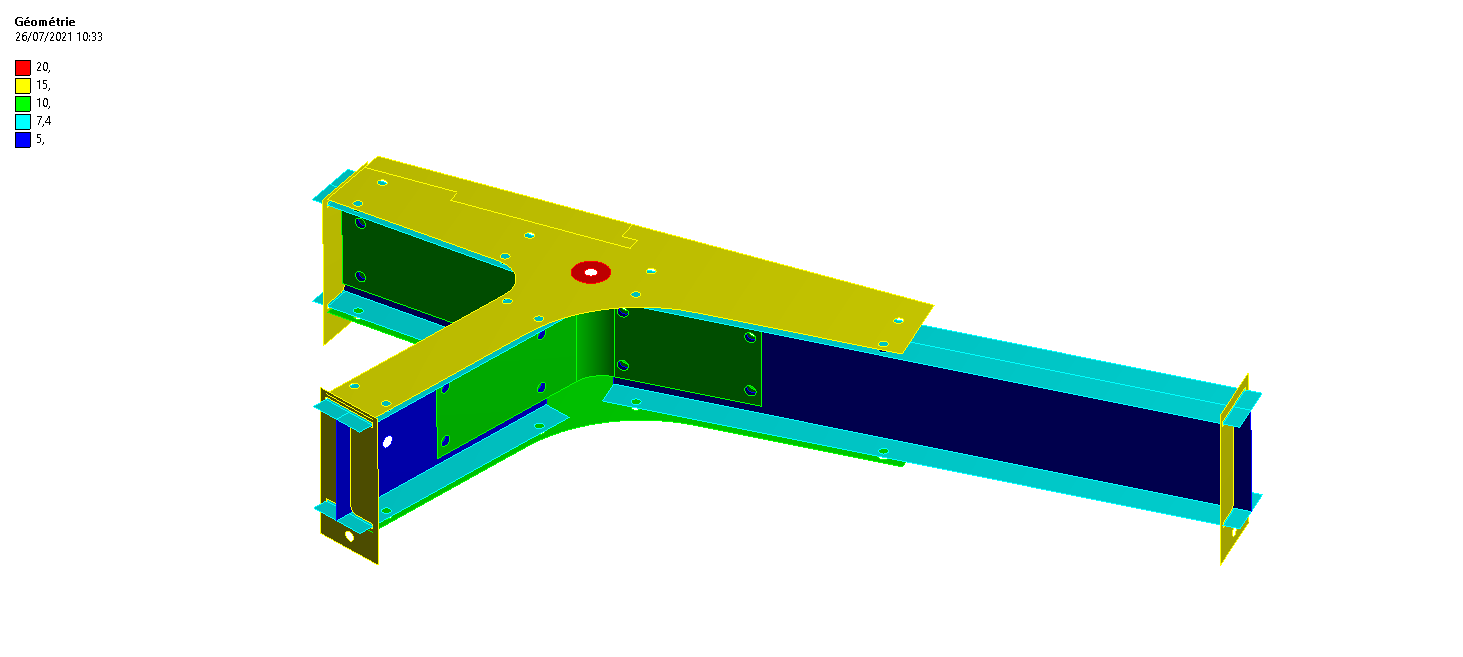
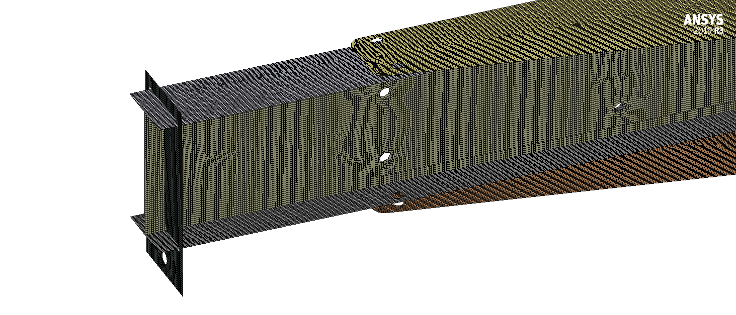
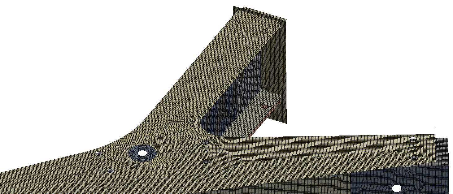
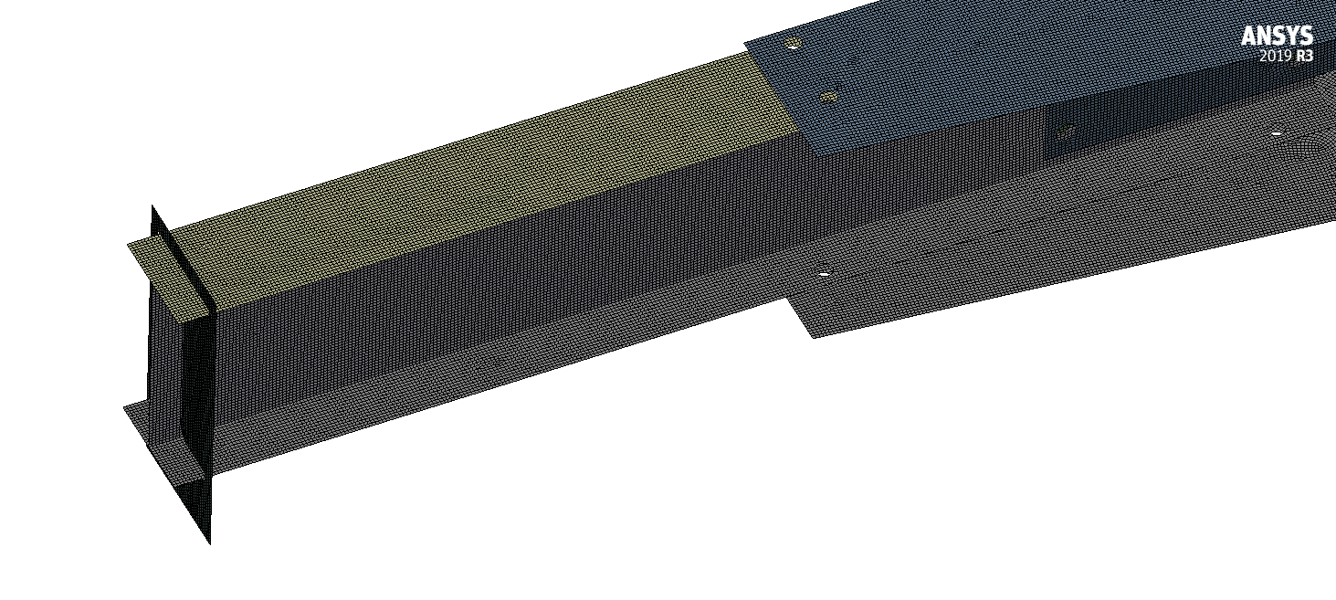
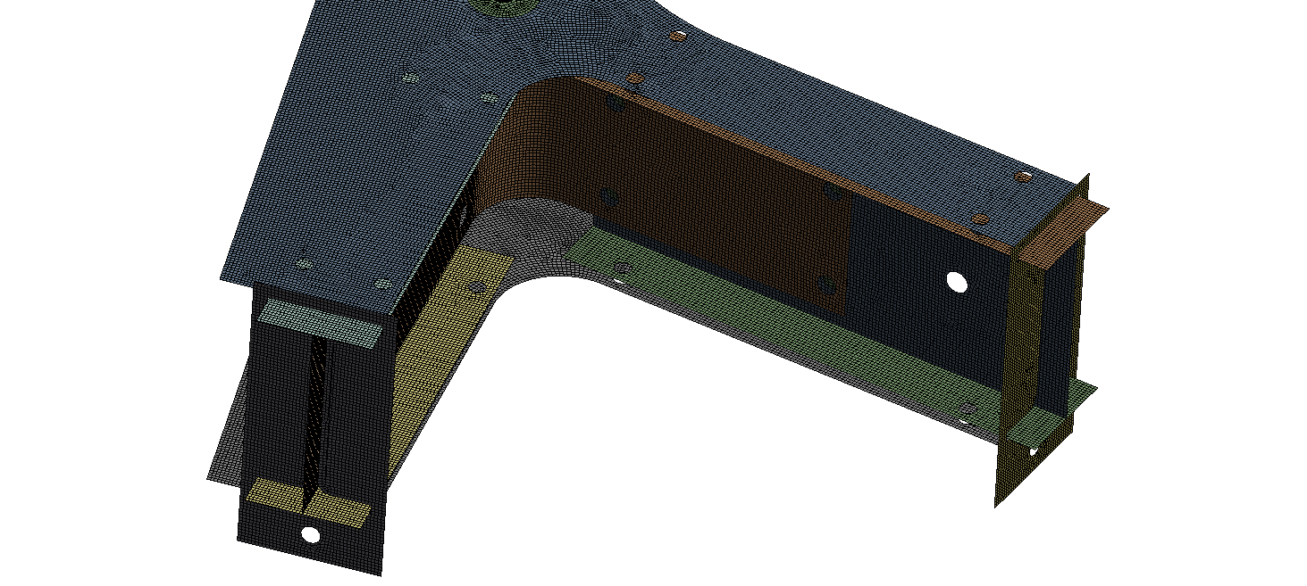
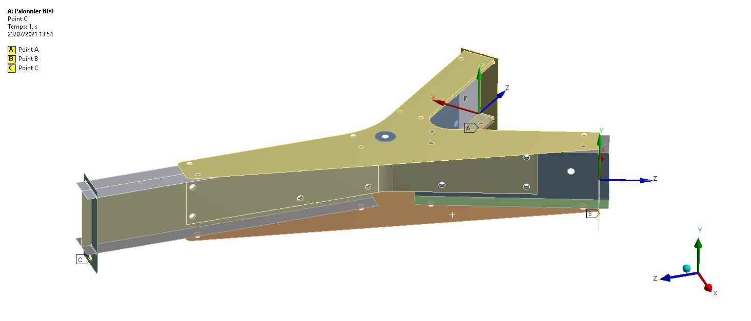
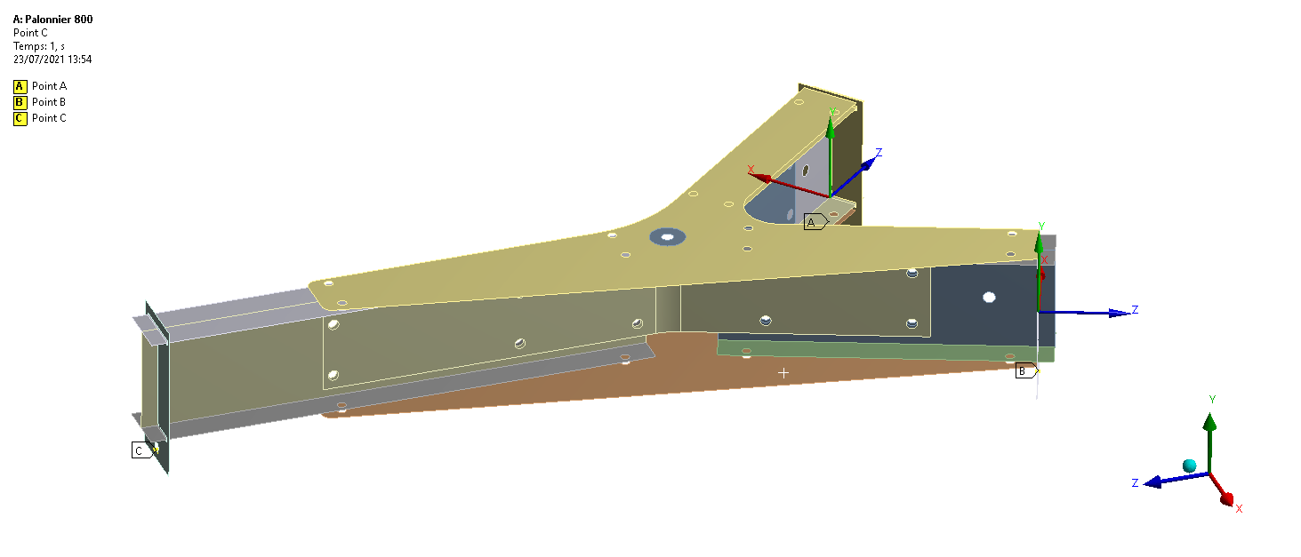
Both lifting beams are simplified at their neutral surfaces and actual thicknesses are assigned to the shell elements to preserve the stiffness of plates, stiffeners and arms.
Model data101.57 kgModel mass — 800 kg lifting beamComplete structure modelled
Model data111.23 kgModel mass — 1,300 kg lifting beamComplete structure modelled
Model data2 configurationsCapacities analysedSWL 800 kg and SWL 1,300 kg
Technical review points- Load cases
- Boundary conditions
- Mechanical response
- Reviewable results
Stage 02Mesh & refinement areas
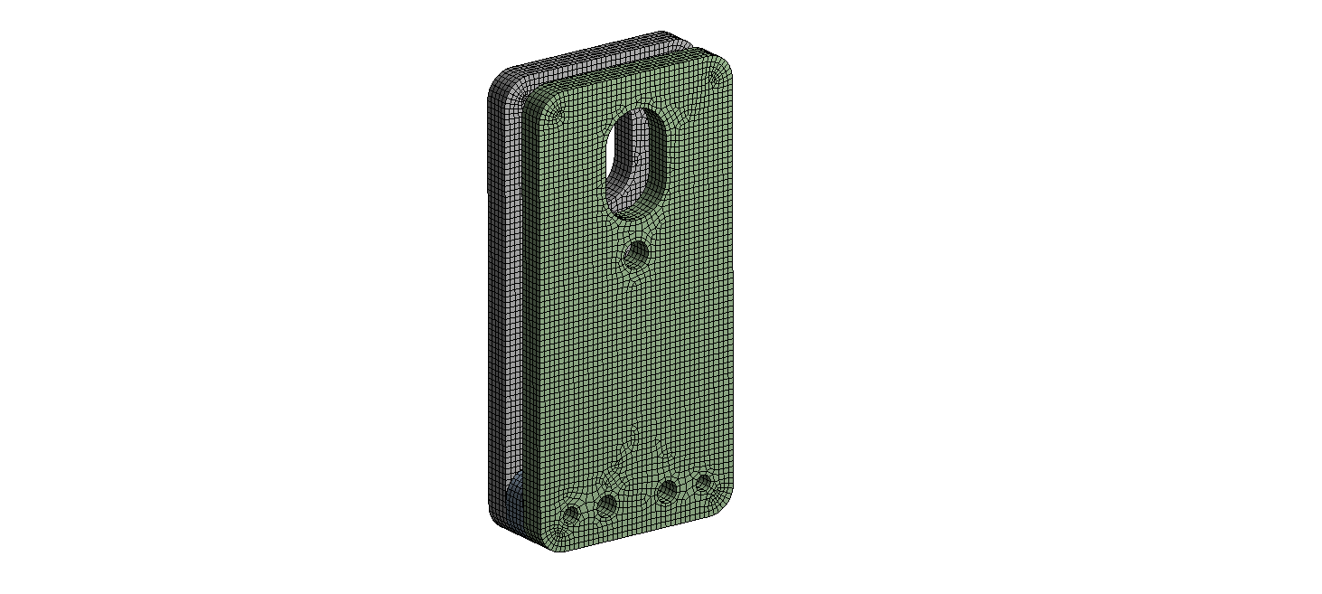
Triangular and quadrilateral surface mesh with detailed control around end plates, central stiffeners and load-transfer areas.
Model data2.5 mmNominal mesh sizeValue applied to the complete model
Model dataTri + quadElement familiesSurface elements for shell models
Model dataS235 / S355Main material gradesProperties assigned part by part
Technical review points- Technical objective
- Interfaces
- Acceptance criteria
Stage 03Contacts, connections & boundary conditions
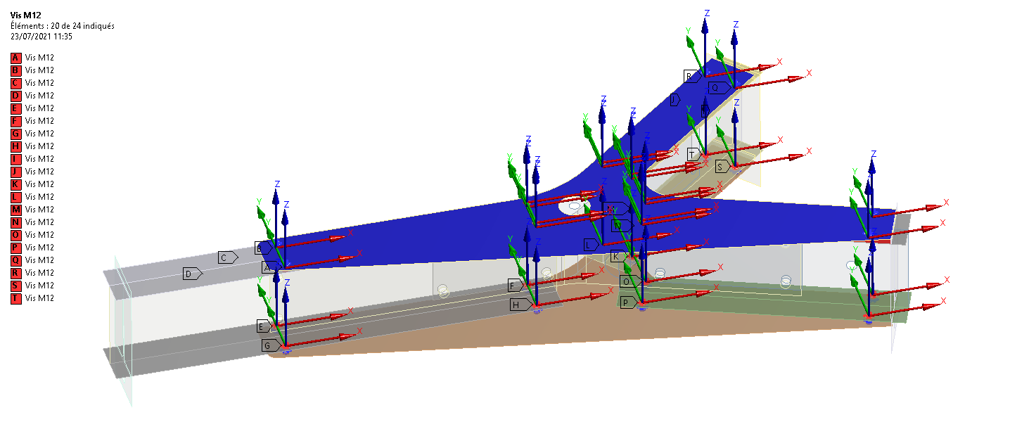
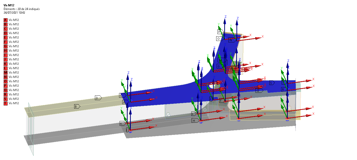
Modelling of welded and bolted assemblies, rigid connections and supports to transfer loads while retaining the degrees of freedom representative of actual operation.
Model dataA · B · CReaction pointsTranslations and rotations defined locally
Model dataWelded + boltedInterfaces representedLoad transfer between subassemblies
Technical review points- Load cases
- Boundary conditions
- Mechanical response
- Reviewable results
Stage 04Load cases & self-weight
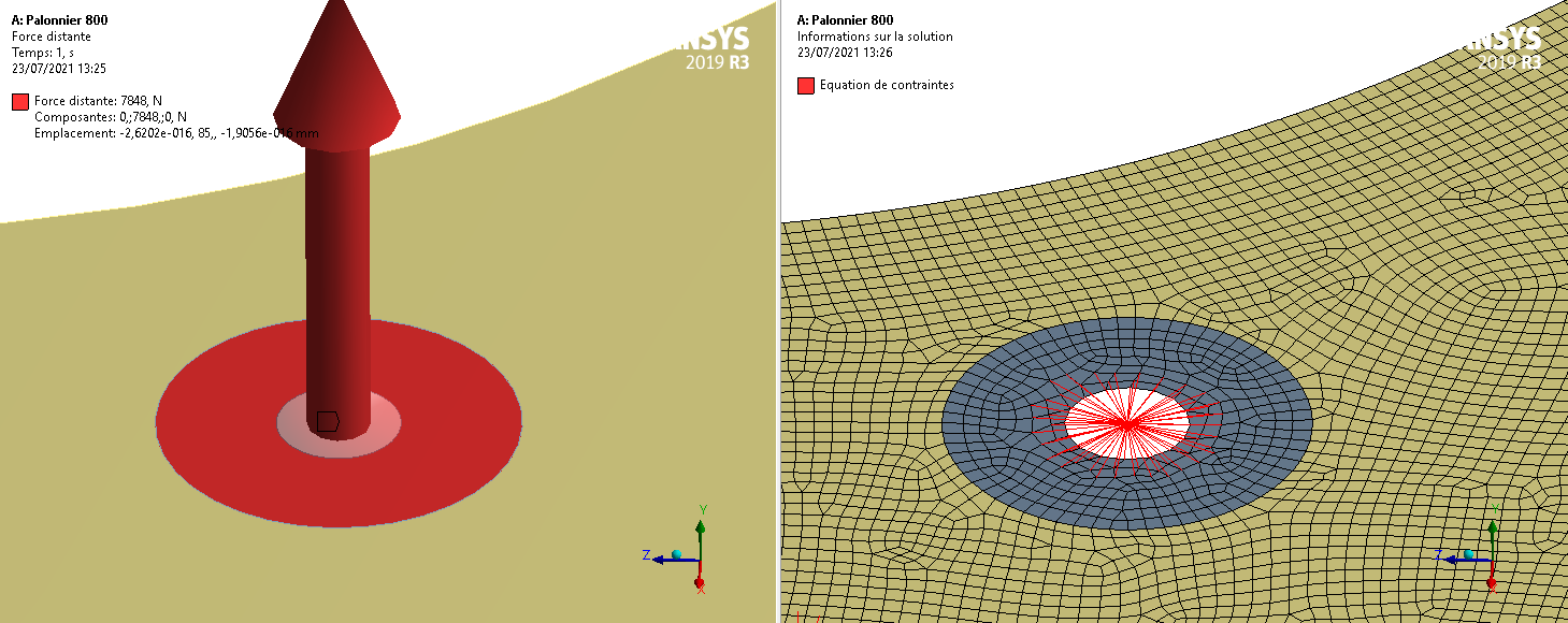
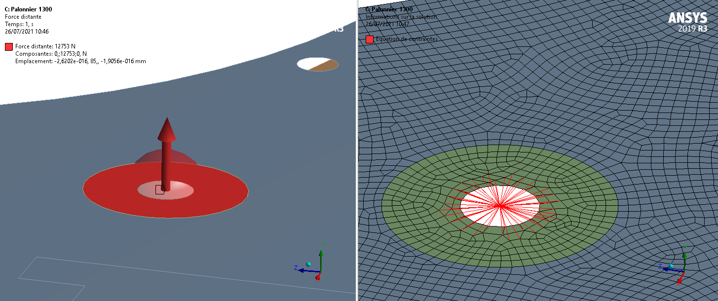
Each SWL is applied to the lifting-eye bearing surface together with structural self-weight to reproduce the vertical load transmitted to the lifting beam.
Model data7,848 NApplied load — SWL 800 kgRemote vertical force
Model data12,753 NApplied load — SWL 1,300 kgRemote vertical force
Model data9.8066 m/s²Gravitational accelerationSelf-weight included
Technical review points- Technical objective
- Interfaces
- Acceptance criteria
Stage 05Lifting-beam stresses & displacements
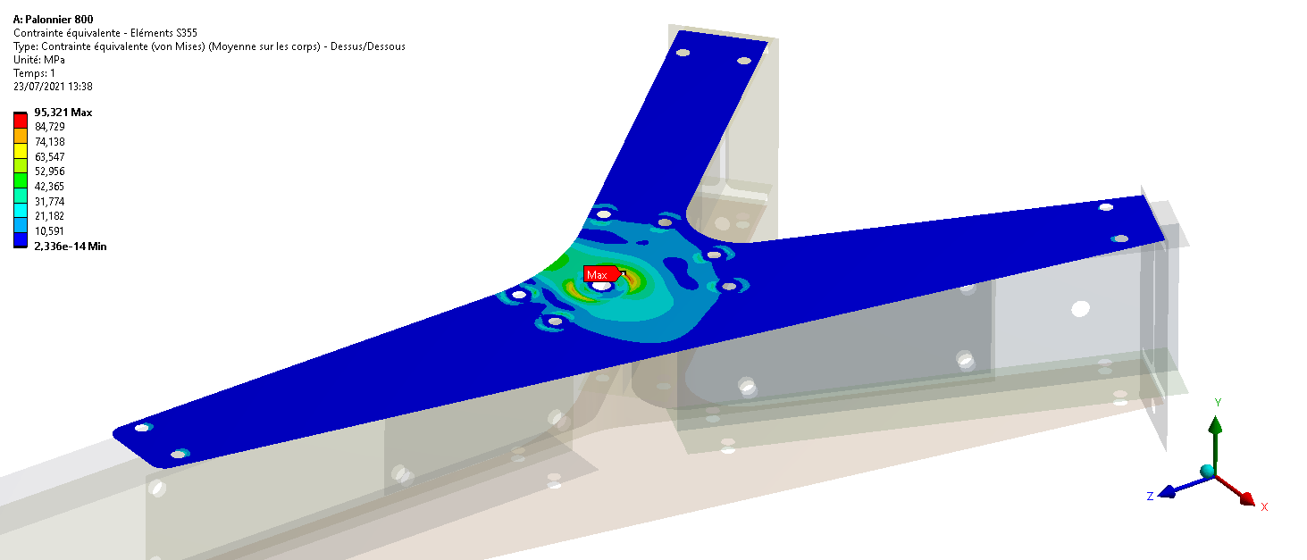
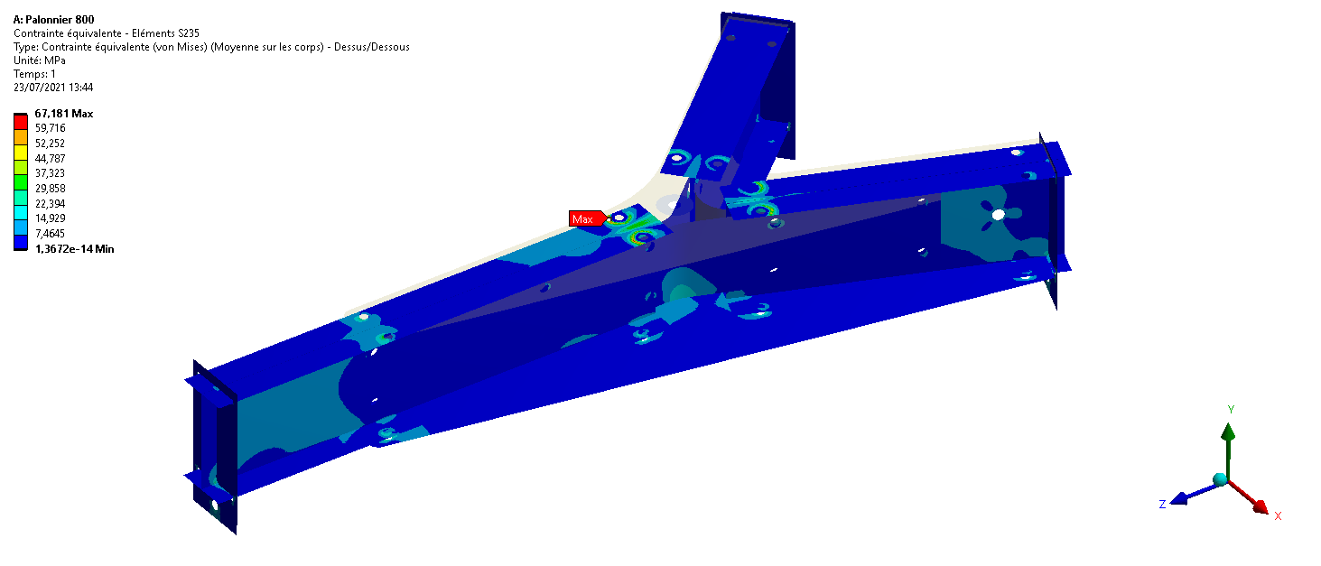
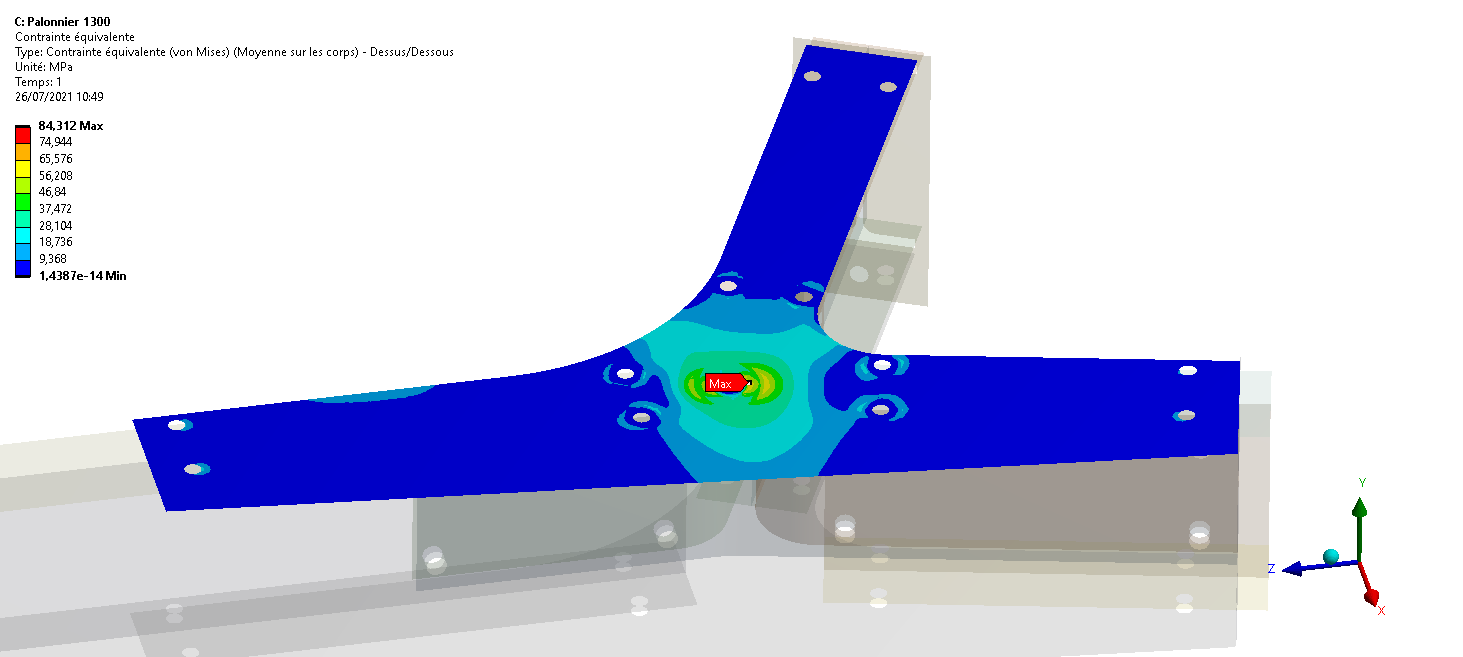
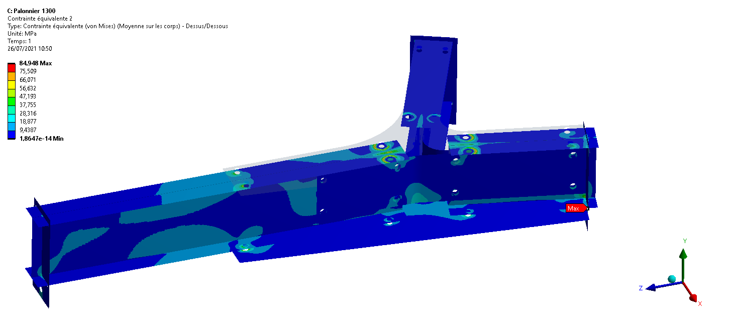
Separate review of Von Mises fields by material grade, control of areas around the lifting interfaces and comparison of global displacements for both capacities.
Validated95.32 / 117.5 MPaS355 — 800 kg lifting beamCalculated / allowable stress
Validated84.95 / 90 MPaS235 — 1,300 kg lifting beamCalculated / allowable stress
Validated0.16 / 0.22 mmMaximum displacementsLifting beams 800 / 1,300
Technical review points- Technical objective
- Interfaces
- Acceptance criteria
Stage 06Lifting plates & assemblies
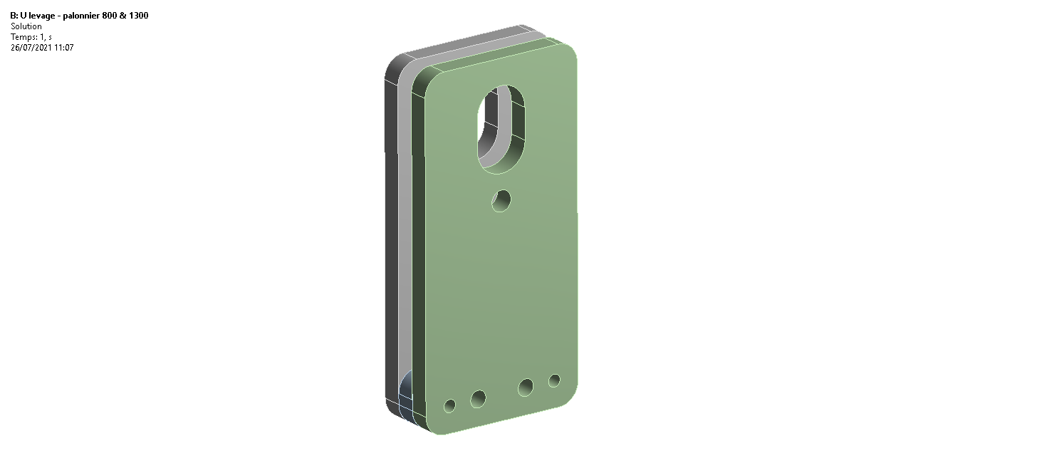
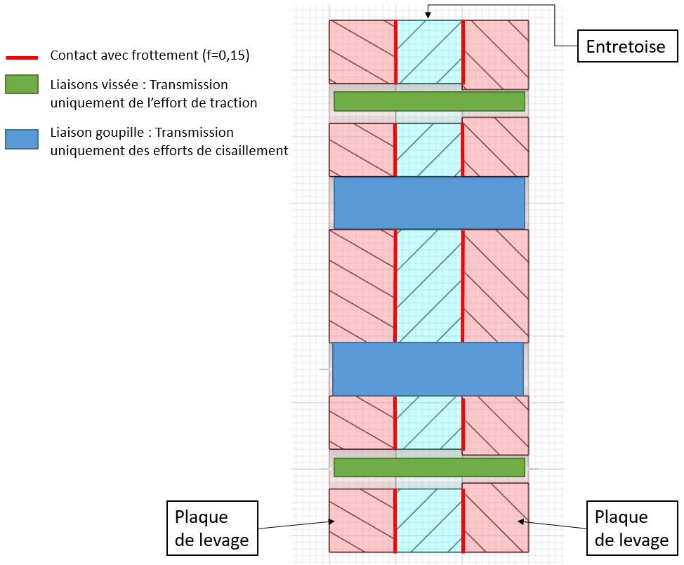
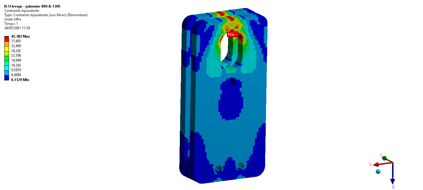
Solid submodel of the lifting plates followed by analytical verification of bolts, threads, pins and commercial components using forces extracted from the global calculation.
Validated42.38 / 90 MPaLifting plates — S235Calculated / allowable stress
Validated192.15 / 200 MPaM12 bolts — equivalent stressGoverning case for the 1,300 kg lifting beam
Validated22.18 / 108.25 MPaØ15 pins — shearCalculated / allowable stress
Technical review points- Technical objective
- Interfaces
- Acceptance criteria